
Figure 312 — Example for concrete box girder bridge
| Format | ASCII | HTML |
|---|---|---|
| IFC-SPF | File | Markup |
| View |
|---|
| Bridge View |
This example illustrates a concrete box girder bridge following horizontal curvature and parabolic slope. The specific bridge is Minneapolis Bridge 27B01 for Van White Memorial Boulevard northbound over BNSF railroad tracks north of junction of Dunwoody Boulevard and I-394.
|
|
Figure 312 — Example for concrete box girder bridge |
| Item | Description | Preview | ||||||||||||||||||||||||||||||||||||||||||||||||||||||||||||||||||||||||||||||||
|---|---|---|---|---|---|---|---|---|---|---|---|---|---|---|---|---|---|---|---|---|---|---|---|---|---|---|---|---|---|---|---|---|---|---|---|---|---|---|---|---|---|---|---|---|---|---|---|---|---|---|---|---|---|---|---|---|---|---|---|---|---|---|---|---|---|---|---|---|---|---|---|---|---|---|---|---|---|---|---|---|---|---|
| Project IfcProject | The project defines units according to the Imperial system. It declares product type definitions for all components, which are then placed and transformed according to the alignment curve. The project aggregates an IfcSite, which contains all physical elements for the bridge. | |||||||||||||||||||||||||||||||||||||||||||||||||||||||||||||||||||||||||||||||||
| Alignment IfcAlignment | There is a single alignment curve, for which all components are placed using IfcRelPositions. The horizontal curve alignment consists of a linear segment followed by a circular curve segment. The vertical alignment curve consists of a linear segment followed by a parabolic segmen and another linear segment. | |||||||||||||||||||||||||||||||||||||||||||||||||||||||||||||||||||||||||||||||||
| Abutments IfcCivilElement | The cheek wall consists of a construction joint, so is modeled by two separate IfcWall instances, where the construction joint is related using the IfcRelConnectsElements relationship, and each instance consists of IfcExtrudedAreaSolidTapered geometry. The southeast wing wall is modeled as a single IfcWall instance based on IfcExtrudedAreaSolidTapered geometry. The southwest retaining wall is modeled as a single IfcWall instance based on IfcFixedReferenceSweptAreaSolid geometry to capture curvature. Footings are modeled using IfcFooting based on IfcExtrudedAreaSolid geometry with IfcArbitraryClosedProfileDef footprint. Piles are modeled using IfcPile based on IfcMappedItem indicating repetitive placement of IfcExtrudedAreaSolid geometry with IfcCircleProfileDef cross-section. Reinforcing within this abutment follows several forms of repetition: linear, linear with angle transition, and staggered (L-shaped instances alternate directions of hooked ends). Reinforcing near piles uses larger bars spaced closer together, compared to smaller bars spaced further together between piles. All rebar shapes are defined within a schedule for this set of plans, where parameters are applied to a set of standard bending shapes, where such information is captured at IfcReinforcingBarType, where the geometry is described using IfcSweptDiskSolidPolygonal. Each usage of a group of bars of the same schedule entry is captured at IfcReinforcingBar, with each bar instance is positioned according to IfcMappedItem. |  | ||||||||||||||||||||||||||||||||||||||||||||||||||||||||||||||||||||||||||||||||
| Piers IfcCivilElement | There are four piers using the same overall geometry but with variable height. Such similarity allows for a template to be used that describes the pier once, and then instantiated four times, where the only parameters that vary are the position and height. However, the plans for this bridge did not use such templated approach, and described each pier separately. The template of piers is modeled as IfcCivilElementType. The IfcCivilElementType contains an ‘Axis’ representation of an IfcPolyline having a single segment of an arbitrary length, which is used to establish parametric resizing behavior. The IfcCivilElementType is aggregated into four components using the IfcRelAggregates relationship to contain IfcPile, IfcFooting, IfcColumnStandardCase, and IfcMechanicalFastener (for the bearing). These components are connected sequentially using IfcRelConnectsPathElements, indicating that each start and end according to connectivity along the ‘Axis’ path. While such relationship indicates physical connectivity that may be used for construction and analytical purposes, this relationship may also be used for instantiation of such template to indicate how components resize. The IfcPile corresponds to 16 shape occurrences forming a 4x4 grid. The pile has a corresponding template, IfcPileType, which defines the geometry using IfcExtrudedAreaSolid based on IfcCircleProfileDef. To indicate the repeat placement, the ‘Body’ representation of IfcPile consists of 16 instances of IfcMappedItem, each indicating the position relative to the ‘Axis’ of the enclosing IfcCivilElementType. The IfcFooting defines the shape of the concrete using IfcExtrudedAreaSolid based on IfcRectangleProfileDef. This footing is aggregated into components for rebar using the IfcRelAggregates relationship to contain IfcReinforcingBar and IfcReinforcingMesh, where one IfcReinforcingBar instance describes lateral rebar forming a complete loop (on the outside in each direction), another IfcReinforcingBar instance describes lateral rebar forming a straight line (on the inside in each direction), and an IfcReinforcingMesh instance describes longitudinal rebar and stirrups forming a cage within the column. While such mesh is primarily part of the adjoining IfcColumnStandardCase, it must be embedded within the IfcFooting before the concrete is poured for the footing; therefore such rebar is aggregated within the IfcFooting rather than the IfcColumnStandardCase. Each rebar assembly is detailed at IfcReinforcingBarType and IfcReinforcingMeshType respectively. Geometry for all rebar types makes use of IfcSweptDiskSolidPolygonal, which allows parametric definition of the bending radius applied at each transition of an IfcPolyline. Geometry for all rebar occurrences makes use of IfcMappedItem to indicate the position and orientation within the IfcFooting relative to the ‘Axis’ representation. The IfcColumnStandardCase captures the variable-height stem of the pier. The “StandardCase” subtype provides for parametric definition here in the same way as done in the general IFC schema, differentiating from the more generic IfcColumn. This IfcColumnStandardCase consists of an ‘Axis’ representation and a relationship to the material cross-section definition using IfcRelAssociatesMaterial linked to IfcMaterialProfileSetUsage. As this column consists of a single circular cross-section, the referenced IfcMaterialProfileSet contains a single IfcMaterialProfile having a reference to IfcCircleProfileDef and IfcMaterial. Concrete strength and other requirements are indicated at IfcMaterialProperties using Pset_MaterialMechanical and others linked to the IfcMaterial instance. | 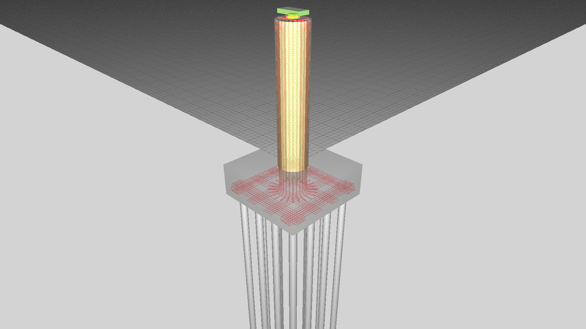 | ||||||||||||||||||||||||||||||||||||||||||||||||||||||||||||||||||||||||||||||||
| Bearings IfcMechanicalFastener | IfcMechanicalFastener captures each pot bearing. Functionally, a pot bearing fits the same definition as already documented at IfcMechanicalFastener, though is of a much larger form factor compared to more common existing uses such as for bolts or bearings used with building equipment. The mechanical behavior of the IfcMechanicalFastener may be described by an assigned IfcStructuralPointConnection, as is done for any physical element having an analytical representation. This IfcStructuralPointConnection defines mechanical degrees of freedom using IfcBoundaryNodeCondition, indicating which axes are fixed and which are free within the range of movement. Each pier instance is modelled using a unique IfcCivilElement instance referencing the IfcCivilElementType. Each IfcCivilElement has a unique ObjectPlacement describing its location, an IfcRelPositions relationship indicating the placement relative to the horizontal curve of the IfcAlignment, and an ‘Axis’ representation indicating the path, which essentially stretches the template to fit according to the specific height. Each IfcCivilElement is connected to the corresponding pier cap beam (IfcBeam) of the box girder using IfcRelConnectsPathElements, where RelatingElement refers to the pier using ‘ATEND’ positioning, and the RelatedElement refers to the box girder using ‘ATPATH’ positioning. Each CivilElement is connected to the ground (IfcGeographicElement) using IfcRelConnectsElements, where volume geometry defines the required ground penetration. Such relationships provide information for applications to automatically resize piers according to the ground and the vertical alignment of the bridge deck. | 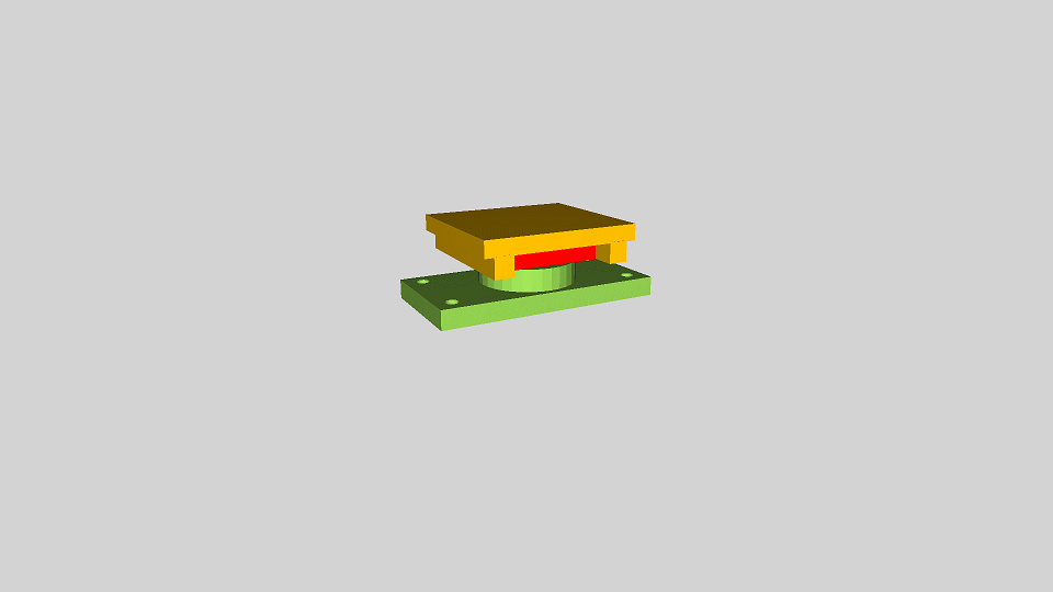 | ||||||||||||||||||||||||||||||||||||||||||||||||||||||||||||||||||||||||||||||||
| Cap beams IfcBeam |
The cap beams are represented by IfcBeam, and make use of a template using IfcBeamType. At the IfcBeamType, geometry for the concrete is captured using IfcExtrudedAreaSolidTapered based on an IfcTShapeProfileDef.
The IfcBeamType is aggregated into components using the IfcRelAggregates relationship, and contains rebar (IfcReinforcingBar), tendons (IfcTendon), tendon anchors (IfcTendonAnchor), and sleeves for conduit (IfcCableCarrierSegment).
Each reinforcing group is captured using IfcReinforcingBar, and links to the backing rebar shape exactly as detailed in the plans (the “Superstructure Bar Lists” pages) linking to IfcReinforcingBarType with the IfcRelDefinesByType relationship. Placement of each bar within the group is indicated using IfcMappedItem. Several repetition scenarios are encountered with rebar in the pier cap beams, as described in the table below, where “Occurrences” indicates the number of IfcReinforcingBar instances and “Items” indicates the number of IfcMappedItem’s within each IfcReinforcingBar, such that the total bars within the cap beam are equal to multiplying Occurrences by Items and totaling each type.
While indicating each bar placement specifically is required for interoperability with existing IFC applications, indicating placement patterns is entirely optional.
|  | ||||||||||||||||||||||||||||||||||||||||||||||||||||||||||||||||||||||||||||||||
| Diaphragms IfcBeam | The diaphragms above the north and south abutments are each represented by IfcBeam, and make use of a template using IfcBeamType. | 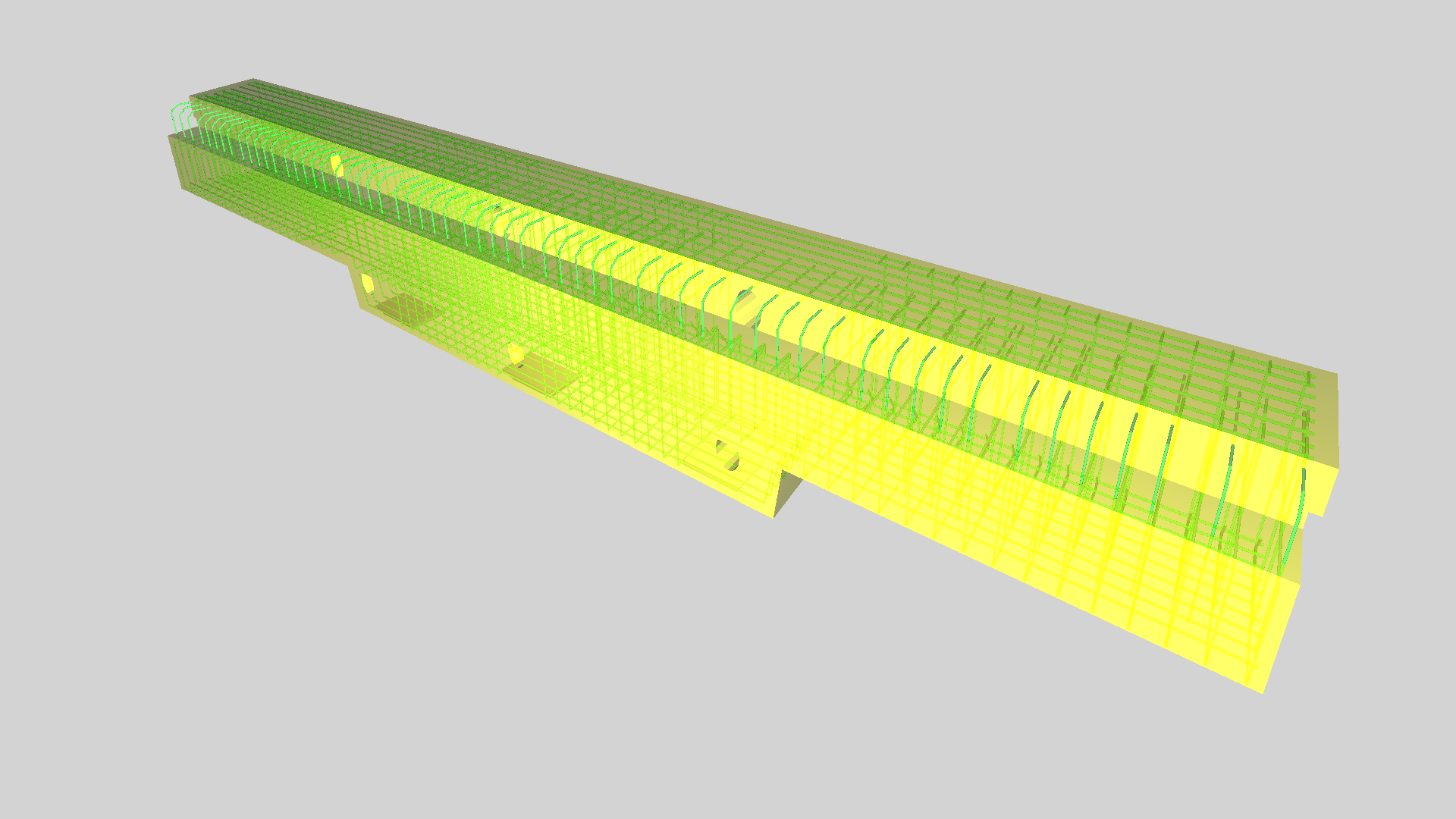 | ||||||||||||||||||||||||||||||||||||||||||||||||||||||||||||||||||||||||||||||||
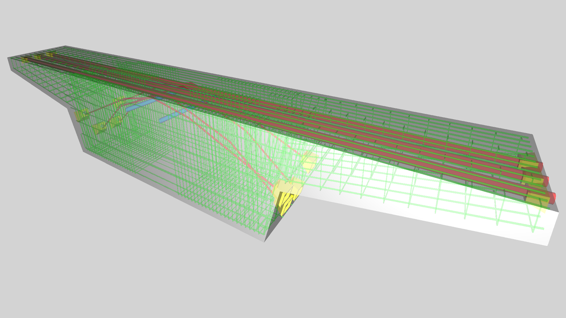
| Box girders IfcBeam | Each of the girder spans is encapsulated within an IfcBeam component and linked to an IfcBeamType which defines the composition. The IfcBeamType uses Cartesian coordinates and assumes extrusion in a constant direction. The IfcBeam occurrence is placed along an IfcAlignment using the IfcRelPositions relationship, where the reflected geometry at the occurrence, including all components, is then transformed into the alignment-based coordinate system, such that +X indicate the longitudinal offset along the alignment curve, +Y indicates the lateral offset to the left with rotation as facing in the direction of the alignment curve, and +Z indicates the vertical offset above the alignment curve with rotation. Each aggregated element at IfcBeamType is reflected underneath the IfcBeam occurrence, where IfcMappedItem of each reflected component is adjusted according to the alignment curve. The IfcBeam occurrence defining Span 1 is connected from the South Diaphragm component and connected to the Pier 1 Cap Beam, each using the IfcRelConnectsPathElements relationship, where RelatingConnectionType is set to ATEND and RelatedConnectionType is set to ATSTART. This relationship indicates that the elements are joined end-to-start along the longitudinal axis (X) according to the extents of the direct “Body” geometry of the IfcBeam. Note that such extents are NOT impacted by embedded components such as rebar or tendons, which may intersect with connected components. The IfcBeam occurrence is connected to the bridge deck above using the IfcRelConnectsPathElements relationship with both RelatingConnectionType and RelatedConnectionType set to ATPATH. The IfcBeam defines camber ordinates within its “Camber” representation using IfcRationalBSpline instances corresponding to each girder. Each curve contains three control points, as defined on plans: the head and tail having Z=0, and the point of maximum camber where X indicates the longitudinal offset and Z indicates the vertical camber where positive is up. The IfcBeamType defines geometry within its “Body” representation using two shapes: an IfcExtrudedAreaSolid for the constant section using IfcArbitraryClosedProfileDef, and an IfcExtrudedAreaSolidTapered for the section near the pier where the soffit slab thickens, also using IfcArbitraryClosedProfileDef. The IfcBeamType is decomposed into components using the IfcRelAggregates relationship, where rebar uses IfcReinforcingBar, tendons use IfcTendon, vent pipes use IfcPipeSegment, drain pipes use IfcPipeSegment, and access panels use IfcDistributionChamberElement. Each tendon group (3 groups of 3) is captured using IfcTendon linked to an IfcTendonType defining geometry using IfcSweptDiskSolid based on IfcRationalBSplineCurve consisting of parabolic segments. Placement of each tendon within the group is indicated using IfcMappedItem. Vent pipes and drain pipes are captured using IfcPipeSegment linked to IfcPipeSegmentType defining geometry using IfcExtrudedAreaSolid with cross-section of IfcCircleHollowProfileDef. Placement of each pipe along its respective span is indicated using IfcMappedItem. | 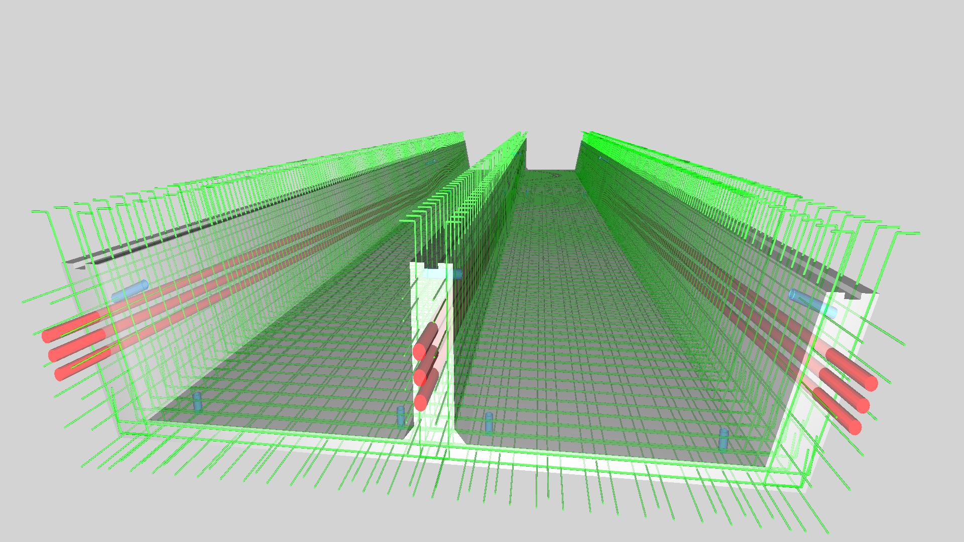 | ||||||||||||||||||||||||||||||||||||||||||||||||||||||||||||||||||||||||||||||||
| Bridge deck IfcSlab | The profile varies along the bridge deck, where the base slab of each section thickens at constant rate near the piers and the overall profile is solid concrete at the cap beams over the bridge piers. Each of these sections are connected sequentially using the IfcRelConnectsElements relationship, implying continuity of concrete (as opposed to IfcRelConnectsWithRealizingElements which would imply a physical connection or construction joint). The slab segments (IfcSlab) use a constant cross-section that rotates. The separation between cap beams (IfcBeam) and spans (IfcSlab) occurs where the cross-section begins to taper (soffit slab thickens) near the piers and abutments. While the deck span segments could also be modelled using IfcSectionedSpine at intervals acceptable for construction, the curvature may be exactly described using IfcSurfaceCurveSweptAreaSolid. This geometry defines both a directrix based on any IfcCurve (including IfcBSplineCurve for precise definition for any arbitrary curve), and a reference IfcSurface (including IfcBSplineSurface for precise definition of any arbitrary surface). For this particular example, an IfcBSplineSurface may be constructed consisting of a ruled surface having two arrays of points along the bridge deck alignment. | 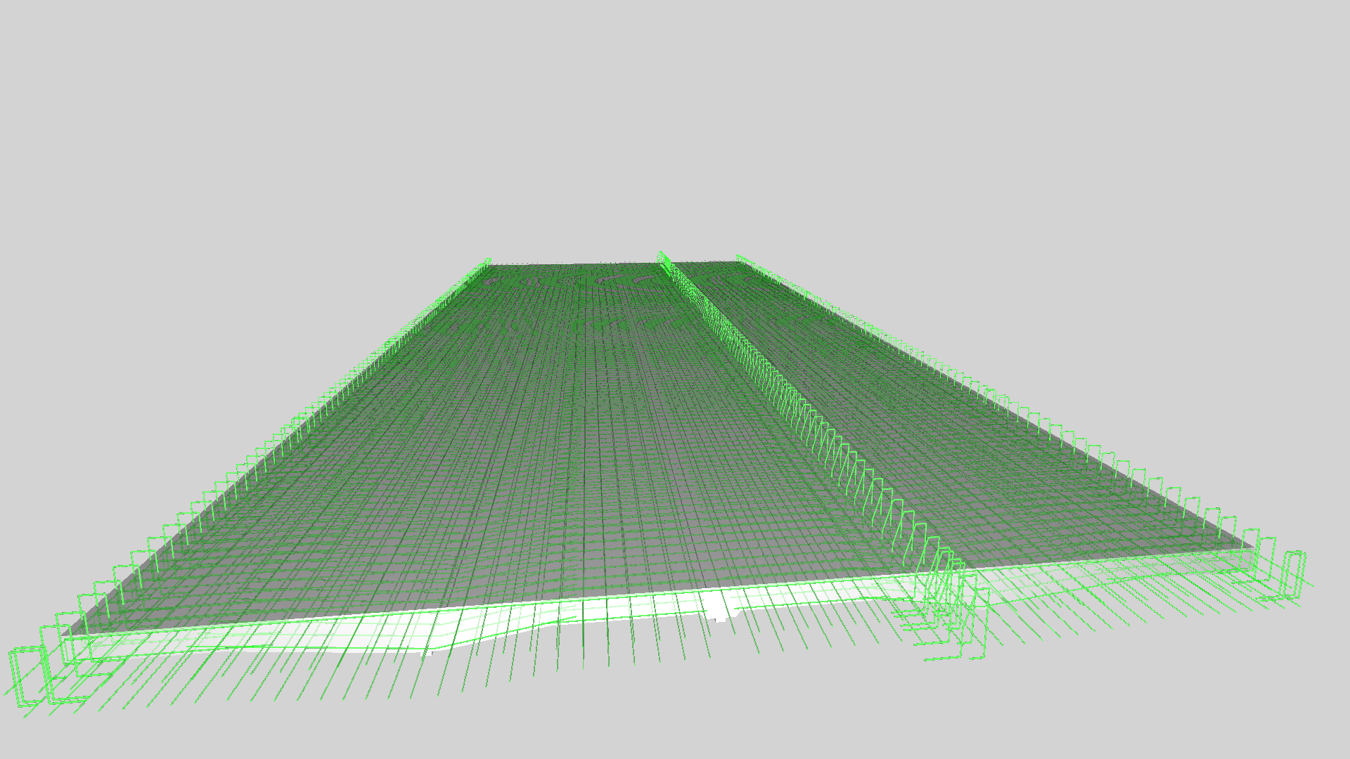 | ||||||||||||||||||||||||||||||||||||||||||||||||||||||||||||||||||||||||||||||||
| Railings IfcRailing | There are three railings on this bridge: the west railing alongside the roadway, the divider between the roadway and walkway, and the east railing alongside the walkway. Each guard rail has railings and light fixtures attached. Type definitions for each railing span are modelled using IfcRailingType, consisting of components for guard rails, ornamental railings posts and spans, light fixtures, conduit, and junction boxes. Each post is defined by IfcMember having PredefinedType=POST. While such IfcMember could be aggregated further into plates and other elements, such composition isn’t warranted (and would be inefficient), as it is assumed that they will be fabricated into solid components before construction. The geometry for plates is described using IfcExtrudedAreaSolid based on IfcArbitraryProfileDefWithVoids, where the outer curve is based on IfcPolyline and the inner holes are defined using IfcCircle. The geometry for hollow sections is described using IfcExtrudedAreaSolid based on IfcRectangleHollowProfileDef. The geometry for angles connecting to railings is described using IfcExtrudedAreaSolid based on IfcLShapeProfileDef. The caps for the dividing railing posts are described using IfcRevolvedAreaSolid based on IfcCShapeProfileDef. The caps for the outer railing posts are described using IfcCsgSolid based on IfcRectangularPyramid. The ornamental railings are modeled using IfcMember with PredefinedType=CHORD, where straight segments are modeled using IfcExtrudedAreaSolid based on IfcRectangleHollowProfileDef, and decorative segments are modeled using IfcFixedReferenceSweptAreaSolid based on IfcRectangleHollowProfileDef. The light fixtures are modeled using IfcLightFixture with geometry defined by IfcTriangulatedFaceSet. As light fixtures are manufactured products that are typically provided in tessellated form, where the exact parameters used to generate the geometry are not of importance, there is no need for any parametric representation. | 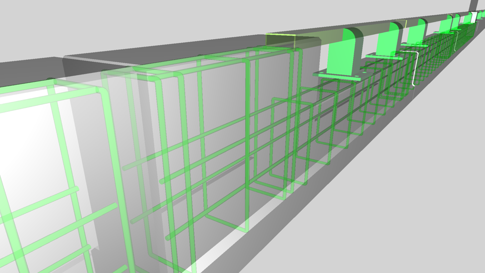 | ||||||||||||||||||||||||||||||||||||||||||||||||||||||||||||||||||||||||||||||||
| Rebar IfcReinforcingBar | Each reinforcing bar group is captured using IfcReinforcingBar, and links to the backing rebar shape exactly as detailed in the plans (the “Superstructure Bar Lists” pages) linking to IfcReinforcingBarType with the IfcRelDefinesByType relationship. Placement of each bar within the group is indicated using IfcMappedItem. Each IfcReinforcingBarType defines geometry using IfcSweptDiskSolidPolygonal, indicating a polyline-based path with a bending radius applied. The NominalDiameter attribute indicates the nominal bar size- for example, 0.625 is equivalent to #5 Imperial and #16 Soft Metric. The BendingCode attribute indicates the standard rebar bending shape according to ACI-318, for example “102” for hooked-U shape stirrups. The BendingParameters attribute indicates parameters applied to the applicable shape (e.g. width, height). | 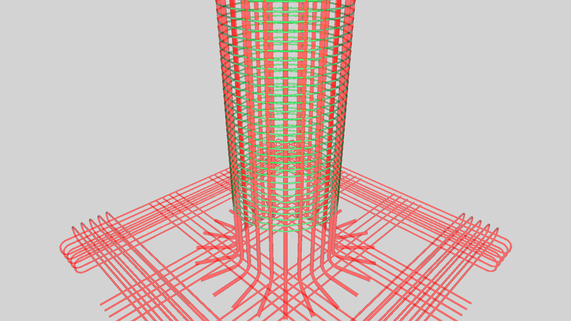 | ||||||||||||||||||||||||||||||||||||||||||||||||||||||||||||||||||||||||||||||||
| Electrical Conduit IfcCableCarrierSegment | Embedded electrical conduit is captured using IfcCableCarrierSegment having PredefinedType=CONDUIT. Junction boxes are captured using IfcJunctionBox, each of which have ports (IfcDistributionPort) connected to one or more IfcCableCarrierSegment elements using IfcRelConnectsPorts. The relationship IfcRelAggregates is used to embed conduit and junction boxes into the enclosing element (e.g. IfcWall, IfcRailing). If conduit spans multiple elements, it may only be embedded within of them and is presumed to interfere with connecting elements, where the embedded element may serve as an anchor for design purposes but otherwise carries no meaning. | 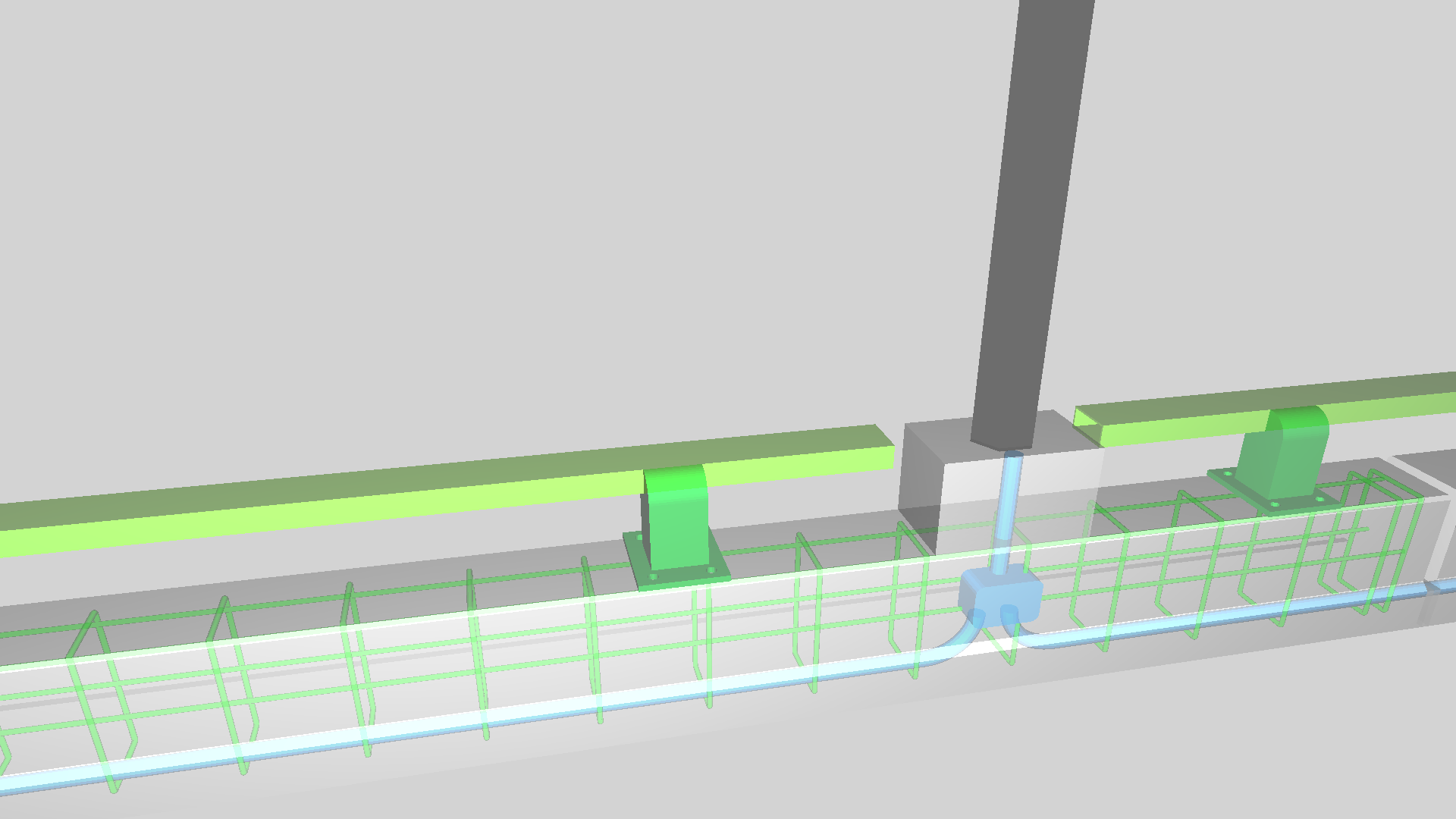 |
 Link to this page